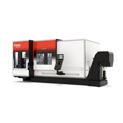
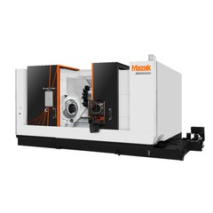
The reason machining centers can undertake the efficient and precise machining of complex parts in modern manufacturing lies in their highly integrated and modular internal structure.The overall structure consists of the machine tool body, CNC system, drive and transmission unit, automatic tool changer, auxiliary systems, and detection and feedback devices. These parts work together to achieve high-speed, high-precision, and multi-process automated machining.
The machine tool body is the basic framework that supports and positions the machining process. It typically consists of a high-rigidity bed, column, slide, worktable, and guide rail assembly. The bed is mostly made of high-quality cast iron or welded steel, and undergoes aging treatment to eliminate internal stress, ensuring dimensional stability during long-term use. The column and slide form a vertical and horizontal support system, while the guide rails use rolling or sliding types, supplemented by pre-tightening and lubrication structures to ensure low friction and high rigidity of the moving parts. The worktable can be divided into fixed and exchangeable trays, depending on the structural form, to meet the needs of continuous machining of multiple workpieces. Common CNC layouts include vertical, horizontal, and gantry types. Vertical layouts are compact and suitable for machining small to medium-sized parts, horizontal layouts facilitate multi-faceted machining, and gantry layouts, with their large stroke and high rigidity, are suitable for large components.
The CNC system is the command center of the machining center, composed of controller hardware and software. It interprets machining program instructions and generates motion trajectories for each coordinate axis and spindle speed control commands. Modern CNC systems often feature multi-axis linkage, high-speed interpolation, look-ahead control, and graphical simulation capabilities, enabling them to handle real-time computational demands for complex surfaces and high-speed machining. Its integration with the human-machine interface (HMI) allows operators to easily edit programs, set parameters, and monitor status.
The drive and transmission unit includes servo drives and feed transmission mechanisms. The servo drive receives commands from the CNC system and, through closed-loop control of current, speed, and position loops, drives the servo motor to achieve high-precision displacement and speed response. Feed drives commonly come in two forms: ball screw pairs and linear motors. Ball screws convert rotary motion into linear motion and are known for their reliability and maturity. Linear motors eliminate intermediate transmission links, providing higher speed and acceleration performance, making them suitable for high-speed machining. The spindle drive unit controls the main motor to achieve stepless speed regulation and constant power output, meeting the needs of different materials and cutting conditions.
The automatic tool changer (ATC) is a key component in machining centers for achieving process concentration. It consists of a tool magazine and a tool changing mechanism. Tool magazines can be classified by capacity and form, including hat-type, disc-type, chain-type, and matrix-type, with capacities ranging from a dozen to hundreds of tools. The tool changing mechanism, driven by a robotic arm or cam, quickly and accurately exchanges tools between the spindle and tool magazine according to programmed instructions during machining, significantly reducing non-cutting time and improving equipment utilization. Standardized design of the tool holder and drawbar ensures the reliability and compatibility of tool changing.
Auxiliary systems encompass subsystems such as cooling and lubrication, chip removal, hydraulics, and pneumatics. The cooling and lubrication system reduces the temperature of the tool and workpiece through cutting fluid or micro-lubrication, flushes away chips, and improves surface quality. The chip removal device promptly transports chips generated during machining to the collection area, keeping the machining area clean and preventing secondary scratches. The hydraulic and pneumatic systems provide power support for the clamping device, tool changer, and protective doors, ensuring rapid and precise operation.
The detection and feedback devices include position detection elements and status monitoring sensors. High-precision position detection devices such as linear scales, encoders, and rotary transformers form a fully closed-loop or semi-closed-loop feedback system, ensuring the positioning accuracy and repeatability of the coordinate axes. Temperature sensors, vibration sensors, and load detection devices can monitor the operating status of the spindle and feed system in real time, providing a basis for preventative maintenance and intelligent diagnostics.
In summary, the machining center's structural design aims for high rigidity, high precision, and high automation. The various functional modules form an organic whole in terms of mechanical load-bearing capacity, motion control, tool management, and process assurance. This integrated structure not only supports the completion of complex processes in a single setup, but also provides a solid physical and technical foundation for high-speed, high-precision and intelligent machining, making machining centers an indispensable core equipment in modern manufacturing.